Posted on and Updated on

Intro to Physical Computing ⁄ Midterm

In the spirit of Halloween and current political events, Marco and I decided to build a talking cyborg Trump head. The head is meant to detect someone’s presence in front of it and speak. We’ve been having problems hooking up the audio playback, and although it is currently not perfected (an amp is needed to increase the output volume, and a solution to the SPI chip selection causing an unresponsive servo has yet to be found), this is it’s current state:

Mr Cyborg Trump provocatively speaks a line originally spoken from Mrs Clinton: “Apologizing is a great thing, but you have to be wrong. I will absolutely apologize sometime, in the hopefully distant future, if I’m ever wrong.”

Parts

  • Rubber Trump mask
  • Stuffing (cotton, bubble wrap)
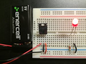
  • Arduino UNO
  • IR motion sensor
  • 8 ohm speaker
  • Servo motor
  • Micro SD card reader and 1gb micro SD card
  • 9v battery pack


Code (Arduino)

#include <SD.h>
#include <pcmConfig.h>
#include <pcmRF.h>
#include <TMRpcm.h>
#include <SPI.h>
#define SD_ChipSelectPin 4
TMRpcm audio;

//using a O O G resistor (3.3 ohms) for IR sensor
//dont delay less than 250 between openMouth & closedMouth

#include <Servo.h>
Servo mouth;

int speakerPin = 3; //digital out
int servoPin = 2; //digital out
int sensorPin = A0; //analog in

int closedMouth = 45;
int openMouth = 180;
int sensorStrength = 500;
unsigned long lengthOfPhrase = 9000; //in milliseconds
unsigned long timePhraseBegin = 0;
boolean movementDetected = false;
boolean speakOnce = false;

void setup() {
  audio.speakerPin = 9;
  Serial.begin(9600);
  mouth.attach(servoPin); 
  mouth.write(closedMouth);

  if (!SD.begin(SD_ChipSelectPin)) {  // see if the card is present and can be initialized:
    Serial.println("SD fail");  
    return;   // don't do anything more if not
  } else {
    Serial.println("SD success"); 
  }
  audio.setVolume(5);
}

void loop() {
  unsigned long timePassed = millis() - timePhraseBegin;
  
  int sensorRead = analogRead(sensorPin);
  
  if(sensorRead > sensorStrength){
    if(!movementDetected){
      Serial.println("ON.");
      timePhraseBegin = millis();
    }
    movementDetected = true;
  } else {
    if(movementDetected && timePassed >= lengthOfPhrase){
      Serial.println("OFF.");
      movementDetected = false;
      speakOnce = false;
    }
  }

  if(movementDetected){
    
    //move mouth
    mouth.write(openMouth);
    delay(250);
    mouth.write(closedMouth);
    delay(250);

    //speak
    if(!speakOnce){
      audio.play("0000.wav");
      speakOnce = true;
    }
    
  } else {
    //close mouth
    mouth.write(closedMouth);

    delay(250);
  }
}

Posted on and Updated on

Intro to Physical Computing ⁄ Week 12 ⁄ Final

Synesthesia VR

Synopsis

Escape into another world.

Synesthesia VR is a device that enables you to experience your surroundings in a new and exciting way. By immersing yourself in this isolated virtual space, you are liberated from the shackles of order and illusions of comprehension, and freed into the higher realm of pure data.

The headset equips you with your very own prosthetic aural and visual sensory inputs which exchange data before feeding into your native senses, in order to ensure complete lack of comprehension of, and thus disconnection from our mundane reality.

Parts

Code

The final Arduino code is below. It uses the Goldelox 4D library (Goldelox is the name of the graphics processor for the LCD displays used, this library implements what the 4D company calls “4DGL” which makes interfacing with the displays very easy), as well as a dedicated library for Sparkfun’s SFE_ISL29125 RGB light sensor. Code for the sound detector can be referenced from here.

/*
 * __________//______//______//____/////____/////__
 * _______////____///__///__//__________//__________
 * ____//____//__///////__//__________//__________
 * ___//////__//__/__//__//__________//__________
 * __//____//__//______//____/////____/////__
 * ___________________________________________________________
 * __________ Copyright (c) 2016 Andrew McCausland __________
 * ________________ <andrewmccausland.net> _________________
 * ________________________________________________________
 * 
 * To upload new code:
 * 1. Disconnect main display (the one that's directly hooked to RX/TX)
 * 2. Disconnect TX connection to display 2
 * 3. Upload
 * 4. Reconnect main display, wait for it to begin visualization
 * 5. Reconnect TX connection to display 2.
 * 
 */

// ------------------------------ visual output (display stuff)
#include "Goldelox_Serial_4DLib.h"
#include "Goldelox_const4D.h"
#define DisplaySerial Serial // The compiler will replace any mention of DisplaySerial with the value Serial 
Goldelox_Serial_4DLib Display(&DisplaySerial);
int width = 127;
int height = 127;
int visOutSwitch = 0;

// ------------------------------ sound input stuff
#define PIN_GATE_IN 2
#define IRQ_GATE_IN  3
#define PIN_LED_OUT 13
#define PIN_ANALOG_IN A0

// ----------------------------- visual input (rgb sensor)

#include <Wire.h>
#include "SFE_ISL29125.h"
SFE_ISL29125 RGB_sensor;

// ----------------------------- sound output

int auxOutPin = 6;
int auxOutSwitch = 0;

void setup() {
  
  // ------------------------------ visual output (displays)
  Display.Callback4D = mycallback;
  Display.TimeLimit4D = 5000;
  DisplaySerial.begin(9600);

  while (!Serial) {
    ; // wait for serial port to connect. Needed for native USB port only
  }
  
  delay (10000); //back up buffer time to let the display start up

  Display.gfx_ScreenMode(LANDSCAPE);

  // ------------------------------ sound input
  pinMode(PIN_LED_OUT, OUTPUT);
  pinMode(PIN_GATE_IN, INPUT);
  attachInterrupt(IRQ_GATE_IN, soundISR, CHANGE);

  // ------------------------------ visual input (rgb sensor)
  
  RGB_sensor.init();
}

void loop() {

  // ------------------------------ for sound input
  int value = analogRead(PIN_ANALOG_IN);

  // ------------------------------ for visual output (display)

  unsigned int blueColors[4] = {MIDNIGHTBLUE,BLUE,DEEPSKYBLUE,LIGHTBLUE};
  unsigned int greenColors[4] = {DARKGREEN,GREEN,GREENYELLOW,LIGHTGREEN};
  unsigned int redColors[4] = {DARKRED,CRIMSON,RED,LIGHTCORAL};
  int brightness = map(value, 0, 600, 0, 3);

  if(value > 80 && value <= 100){
    
      Display.gfx_RectangleFilled(0, 0, width, height, blueColors[brightness]);
      visOutSwitch = 0;
      
  } else if(value > 100 && value <= 200){
    
    if(visOutSwitch == 0){
      Display.gfx_RectangleFilled(0, 0, width, height, blueColors[brightness]);
      visOutSwitch++;
    } else {
      Display.gfx_RectangleFilled(0, 0, width, height, greenColors[brightness]);
      visOutSwitch = 0;
    }
    
  } else if(value > 200 && value <= 600){
    
    if(visOutSwitch == 0){
      Display.gfx_RectangleFilled(0, 0, width, height, blueColors[brightness]);
      visOutSwitch++;
    } else if(visOutSwitch == 1){
      Display.gfx_RectangleFilled(0, 0, width, height, greenColors[brightness]);
      visOutSwitch++;
    } else {
      Display.gfx_RectangleFilled(0, 0, width, height, redColors[brightness]);
      visOutSwitch = 0;
    }
    
  } else if(value > 600){
      Display.gfx_RectangleFilled(0, 0, width, height, WHITE);
      visOutSwitch = 0;
  }

  if(value > 5){
    Display.gfx_Cls(); //clear the screen
  }


  // ------------------------------ for visual input (rgb sensor)
  unsigned int red = RGB_sensor.readRed();
  unsigned int green = RGB_sensor.readGreen();
  unsigned int blue = RGB_sensor.readBlue();

  // ----------------------------- for sound output
  if(auxOutSwitch == 0){
    tone(auxOutPin, red,200);
    auxOutSwitch++;
  } else if (auxOutSwitch == 1){
    tone(auxOutPin, green,200);
    auxOutSwitch++;
  } else {
    tone(auxOutPin, blue,200);
    auxOutSwitch = 0;
  }

}

// ------------------------------ for display
void mycallback(int ErrCode, unsigned char Errorbyte) {
  // Pin 13 has an LED connected on most Arduino boards. Just give it a name
  int led = 13;
  pinMode(led, OUTPUT);
  while(1){
    digitalWrite(led, HIGH);   // turn the LED on (HIGH is the voltage level)
    digitalWrite(led, LOW);    // turn the LED off by making the voltage LOW
  }
}

// ------------------------------ for sound input
void soundISR() {
  int pin_val;

  pin_val = digitalRead(PIN_GATE_IN);
  digitalWrite(PIN_LED_OUT, pin_val);   
}

Posted on and Updated on

Intro to Physical Computing ⁄ Final Project Outline

I want to use what I’ve learned in this class to focus on approaching the use of video and sound in unique ways. So for my final project I want to build some sort of visual and/or auditory headset that transforms the user’s surroundings in unexpected ways, perhaps enabling them to see an aspect of reality that the naked human body isn’t capable of perceiving.

In the spirit of current VR hype, I will build a headset that simulates an audio-visual synesthetic experience, for any curious individuals interested in having a temporarily destroyed sensorium while running the risk of bumping into walls, stubbing their toes or meandering out into traffic in a manner similar to how someone in the throes of an intense psychedelic experience might do so.

The headset will consist of a visual input (camera) and an audio input (sound detector) hooked up to an Arduino Uno, which will run a program that will take the sound data and output it to a color LCD display or two, and take the camera image data and output it to a standard (3.5mm) headphone jack with which the user listen to with their own headphones.

Video to audio: I will translate the color information from the camera image at each frame to tones — a tone for each color. It could either calculate the most prevalent color and translate that into one tone, or calculate all existing colors in each image and translate them into a polyphonic set of tones, or anything in between.

Audio to video: Amplitude of sound detected will translate to image opacity on the display, and pitch/frequency will translate to hue.

Bill of Materials:

System Diagram:

Roadmap:

Nov 16:

  • Have purchased all parts (or at least enough to begin assembly)

Nov 23:

  • Have begun writing and testing code portion
  • Continue circuit assembly
  • Begin circuit housing / headset assembly

Nov 30:

  • Have completed code portion
  • Finalizing circuit assembly, begin user testing
  • Continue circuit housing / headset assembly

Dec 7:

  • Apply changes from user testing
  • Finalize circuit housing / headset assembly
  • Prepare presentation, finalize documentation

Dec 14:

  • Present

Posted on and Updated on

Intro to Physical Computing ⁄ Week 4 ⁄ Lab

Servo

Variable resistor (FSR) triggering servo rotation using the code given in the lab.

A display pedestal, activated via push-button. Behold — coffee.


Tone

Following the tone lab I created a noise instrument using two 8 ohm speakers, four buttons hooked up to analog pins, one button hooked up to digital, and three potentiometers.

Controls from top to bottom: volume, four notes (A2, C2, E2, G2), a fifth note or variable frequency controlled by the potentiometer just below it, and finally a delay effect.

The code for this setup (pitches.h file on this page):

#include "pitches.h"

const int threshold = 10;
const int speakerPin = 8;
const int noteDuration = 20;
 
int notes[] = { NOTE_A2, NOTE_C2, NOTE_E2, NOTE_G2 };

void setup() {}
 
void loop() {
  for (int thisSensor = 0; thisSensor < 4; thisSensor++) {    

  int sensorReading = analogRead(thisSensor);
   
  if (sensorReading > threshold) {
        tone(speakerPin, notes[thisSensor], 20);
    }
  }

  int sensorReading2 = map(analogRead(4), 662, 1023, 50, 2000);
  if(sensorReading2 < 0){
    sensorReading2 = 0;
  }
  if(digitalRead(3) == HIGH){
    tone(speakerPin, sensorReading2, 20);
  }

  int sensorReading3 = map(analogRead(5), 662, 1023, 0, 100);
  if(sensorReading3 < 0){
    sensorReading3 = 0;
  }
  delay(sensorReading3);
}


Posted on and Updated on

Intro to Physical Computing ⁄ week3 ⁄ Observation

Myrtle-Wyckoff Avs Station Main Turnstiles

The purpose of a NYC subway entry/exit mechanism is to enable the MTA to collect and control payment issued by customers for their service, and likely also for collecting rider statistics. This machine has two points of interaction: the card swipe, and the turnstile. The ideal usage consists of the user walking through the mechanism with little to no pause while carrying out this interaction:

  1. Swiping card through slot
  2. Reading visual response from LCD display (“go”, “swipe again”, “insufficient fare”) and/or audible cue
  3. Pushing through the turnstile

Before observing this in action, I had made assumptions about what I’d see. My assumptions were more or less correct because I have over seven years of daily interaction with this machine. Regardless, I had never taken the time to specifically observe their use. My main assumption was that the turnstiles are specifically designed to be used without pause to account for the fast-paced, crowded, and therefore high stress liminal environment for which it resides; most users will not stop while interacting with the machines.

What I observed was on average true, but there appeared to be many “edge cases”: entering users with their hands full of bags, suitcases, carts, etc requiring them to stop in front of or near the machines to pull out their metro card before swiping through. Some would have to bypass the machines altogether and instead enter through the emergency exit with the aid of a subway attendant or another user. When there are multiple users attempting to enter and exit through the turnstiles simultaneously, their tentative coordination and re-routing among the limited number of turnstiles causes congestion.

A minority of users would have difficulty getting the machine to read their metro card, stopping to swipe more than once before being granted entry. I noticed that there’s an audible “click” sound of the turnstile being unlocked for entry after a successful swipe which enabled most users to more quickly recognize if their swipe was successful. There also appeared to be multiple convenient spots where visual/light-symbol indicators should be along the front of the turnstile fixture, but were not functioning on this particular one. The machine responds to every swipe without any noticeable “thinking” time.

I observed that the turnstiles themselves were unquestionably intuitive/natural to all users, either because of their cylindrical shape and position eluding to a “push” interaction, or because turnstiles are simply ubiquitous (or both). The turnstiles caused no issues for anyone.

The turnstile fixtures appear to impose little to no emotional affect on its users, they are simplistic and discreet, enabling the important parts (the light symbols, the LCD display, the swipe slot and the turnstile) to be the central focal points. This design choice fits the context of the fast-paced liminal space which it inhabits.

Posted on and Updated on

Intro to Physical Computing ⁄ week3 ⁄ Lab

Digital Input and Output with an Arduino

Momentary switch going into digital input with pull-down resistor, and two digital outputs controlling LEDs. If button pressed, yellow LED turns on. If button released, red LED turns on.

    void setup() {
    	pinMode(2, INPUT);
    	pinMode(3, OUTPUT);
    	pinMode(4, OUTPUT);
    }

    void loop() {
    	if (digitalRead(2) == HIGH) {
    		digitalWrite(3, HIGH);
    		digitalWrite(4, LOW);
    	}
    	else {
    		digitalWrite(3, LOW);
    		digitalWrite(4, HIGH);
    	}
    }

Combination Lock

Push a set of three buttons in the right order to “unlock” — LED turns on when successful. The correct combo, as seen in code as well as the image above, is btn1, btn3, btn2. There’s also a reset button to erase current combo input and start over.

byte btn1 = 2;
byte btn2 = 3;
byte btn3 = 4;
byte resetBtn = 5;
byte led = 13;

bool doOnce = false;
int counter = 0;
int myPins[] = {2, 4, 8, 3, 6};
int combo[] = { 0, 0, 0};
int correctCombo[] = {2, 4, 3};

void setup() {
  Serial.begin(9600);
  pinMode(2, INPUT);
  pinMode(3, INPUT);
  pinMode(4, INPUT);
  pinMode(5, INPUT);
  pinMode(13, OUTPUT);

  digitalWrite(led, LOW);
  digitalWrite(resetBtn, LOW);
}

void loop() {
  
  if(digitalRead(resetBtn) == HIGH){
    reset();
  }

  if(counter < 3){
    
    digitalWrite(led, LOW);
    
    if(digitalRead(btn1) == HIGH && !doOnce){
  
      combo[counter] = 2;
      counter++;
      
      Serial.print("Btn1 pressed. ");
      doOnce = true;
    }
    if(digitalRead(btn2) == HIGH && !doOnce){
  
      combo[counter] = 3;
      counter++;
      
      Serial.print("Btn2 pressed. ");
      doOnce = true;
    }
    if(digitalRead(btn3) == HIGH && !doOnce){
  
      combo[counter] = 4;
      counter++;
      
      Serial.print("Btn3 pressed. ");
      doOnce = true;
    }
  } else {
    if(combo[0] == correctCombo[0] && combo[1] == correctCombo[1] && combo[2] == correctCombo[2]){
      digitalWrite(led, HIGH);
      Serial.print("Combination succeeded! ");
    } else {
      reset();
      Serial.print("Combination failed. ");
    }
  }
  
  if(digitalRead(btn1) == LOW && digitalRead(btn2) == LOW && digitalRead(btn3) == LOW){
    doOnce = false;
  }

  if(counter == 3){
    
  }
}

void reset(){
  counter = 0;
    combo[0] = 0;
    combo[1] = 0;
    combo[2] = 0;
    Serial.print("Reset. ");
}

Analog In

Using an FSR and an RGB LED, I made a simple weight scale, consisting of a pad (regular perforated cardboard with the sensor stuffed in) that visualizes the weight of objects placed on top of it with the color of the LED — green being lightest, red being heaviest.

const int redLED = 11;
const int greenLED = 10;
const int blueLED = 9;
int sensorValue = 0;

void setup() {
  Serial.begin(9600);
  pinMode(redLED, OUTPUT);
  pinMode(greenLED, OUTPUT);
  pinMode(blueLED, OUTPUT);
}

void loop() {
  
  sensorValue = analogRead(A0); // read the pot value
  int brightness = map(sensorValue, 0, 1024, 255, 0);
  int brightness_g = map(sensorValue, 0, 1024, 0, 255);
  int brightness_r = map(sensorValue, 0, 1024, 255, 0);

  analogWrite(redLED, brightness_r);
  
  if(brightness == 255){
    analogWrite(greenLED, 255);
  } else {
    analogWrite(greenLED, brightness_g);
  }
  
  analogWrite(blueLED, 255);
}

Posted on and Updated on

Intro to Physical Computing ⁄ week2 ⁄ Lab

Lab: Electronics

1

LED receiving 5v.

LED receiving 5v when button (momentary switch) pressed.

2 LEDs in series, each receiving about 2.5v when momentary switch pressed. They are just barely bright enough to see lit. With 3 LEDs, their voltage is too low (needs to be at least ~2v) to see.

3 LEDs in parallel. They each receive 5v of electricity.

Generating a variable voltage with a potentiometer.


Lab: Switches — FX Pedal

A switch made from an FX pedal and and sleeve to go around the user’s foot. When the user presses the pedal with their foot, the sleeve’s conductive surface completes the circuit inside the pedal, causing the BUTT light to illuminate. This is not necessarily an improvement to the original FX pedal button switch for the context that these pedals are usually used, but it at least illustrates possible interactions for other purposes in which a foot wearable could be useful.

Posted on and Updated on

Intro to Physical Computing ⁄ week1 ⁄ What makes good interaction?

Response to The Art of Interactive Design: A Euphonious and Illuminating Guide to Building Successful Software by Chris Crawford, and A Brief Rant on the Future of Interaction Design by Bret Victor.


What is physical interaction?

Interaction is essentially two-way communication. Chris Crawford likened human-computer interaction to a conversation, breaking down the communication cycle into discrete parts: listening, thinking, and responding (input, process, and output, respectively). “Physical interaction” specifically emphasizes the listening and responding aspects of the cycle, as the only way to listen and respond is through some form of physical contact.

What makes for good physical interaction?

An important point Crawford makes regarding his definition of interaction is that not all interactions are created equal — there are varying degrees for which things are able to receive, process, and respond to given information effectively; some things are considered to have high interactivity while others low. Our current landscape of interactive tech is dominated mostly by the visual and less so the audible information in the form of “two-and-one-half dimensional” (as Crawford accurately poised the common display as “a stack of partially overlapping planar images”) UIs. Touch has also been a vital aspect of such software interaction, but still with extremely low interactivity according o Crawford’s logic. This is exactly the point designer Bret Victor makes in his famous A Brief Rant on the Future of Interaction Design essay — touch interactivity is abysmally low, while the emphasis on vision as the main communication medium is unwarranted. Victor points out the reality of how our senses function together: “when working with your hands, touch does the driving, and vision helps out from the back seat.” Instead, our hands (and, by extension, the rest of our bodies) are not nearly being used to their full potential.

Good physical interaction would be that which utilizes the human sensorium to its full potential, incorporating it as effectively as possible into the listening and responding aspects of the interaction cycle.

Does digital technology have anything new or revolutionary to offer which isn’t interactive?

I agree with Crawford’s statement that interactivity is software’s competitive advantage against other mediums, but digital technology as a whole has absolutely improved on the non-interactive mediums that predate it, through its fundamentally algorithmic properties. Its influence can be seen across the board, from music to visual art. It has also enabled various mediums to interact with one another in ways that weren’t necessarily able to be realized before.